Taking pictures to use for photogrammetry
Recommended camera specs
- Digital camera
- 5 megapixels or more
- Lens where focal length = 50/crop factor
- Eg 50 mm lens with a full frame sensor (crop factor 1)
- fixed or prime lens (no zooming)
Tips for taking pictures
- Too many images > not enough, can always remove them in the program itself
- High degree of overlap – only geometry visible in 2+ images will be captured as points by the photogrammetry software
- If indoors, usually better to take the pics looking “inwards” to the middle of the room, even if trying to capture walls- it’ll capture the opposing wall with a much wider shot
- Physical camera should be moved while taking pics, not just rotated
What is difficult to capture
- Small occlusions like tree branches and hair are really hard to get because they overlap with each other and it’s difficult for the system to tell them apart
- Cracks and holes can be difficult because the camera can’t see inside them
- Perfectly flat things are difficult
- Reflective and refractive surfaces are also difficult
- Motion: metashape can’t handle it and photos will have noise and/or not be aligned well
Lighting for taking the pictures
- As bright and even lighting as possible. Large diffuse lights are best
- Don’t include the light sources themselves in photos
- Avoid hot spots (very shiny and bright reflections of the light source)
- Don’t mix light temperatures
- For natural lighting, outdoors on an overcast day can be perfect
Camera settings to use / Tips to improve the final cloud / mesh quality
- Use the lowest possible ISO (100 or less)
- Use high aperture (f/16 if full-frame camera) so as to get wide angle
- Use tripods to avoid blur from slow shutter speeds
- Save in RAW format (convert to TIFF), shoot at max resolution
- Having “interesting” background imagery helps in alignment
- To make background removal easier (if you want that), take pics of just the background or use a background that is very different than the subject
Common reasons photos fail
- Not enough overlap (should have 80% between an image and any adjacent neighbors)
- Poor focus or too much grain
- Images that are cropped, rotated, warped, or resized
- Inaccurate or missing EXIF data
- Lens distortion too extreme (like if the camera used a fisheye lense)
Prepping images for metashape
- Don’t crop, resize, rotate, or warp
- Minor brightness or contrat adjustments are OK
- Convert RAW to TIFF (use Photoshop’s Image Processor script to automate)
Basic Workflow
This is the basic, easiest way to start with photos and get a mesh out at the end. There are other things you can do to increase flexibility, decrease noise, etc, that will be discussed in [Advanced Workflow]
Import
- If all image files are in one folder, Workflow->Add folder
- Else, from the top bar, click Workflow->Add photos until all photos have been imported
Check Quality
- Click on the Photos pane on the bottom
- Right click, Estimate Image Quality
- Once that loads, discard images below 0.5 (this will be one of the columns when the photos are shown in details mode

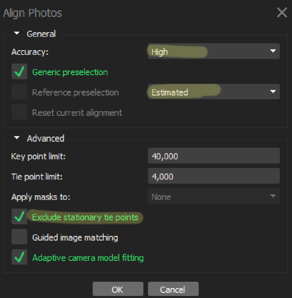
Align
- Workflow->Align Photos
- Recommended: High Accuracy
- If you have many photos, Generic preselection
- If photos are named sequentially, ie taken one after another while moving the camera in a simple fashion, choose Sequential. Else, choose Estimated
- If using a turntable setup, Exclude stationary tie points
Edit Bounding Box to only include what we care about
- In the toolbar right before the top menu, use the movement tool (looks like an arrow) and the reconstruction volume tools (looks like a box with arrows, or corners, or a hand). You can switch between reconstruction volume tools using the dropdown to the right of the tool itself
- You can move around the scene by
- LMB click and drag to rotate, centered around the gray sphere in the middle of the screen
- RMB click and drag to pan around the screen
- MMB scroll to zoom in/out
- You can edit the volume by moving the corners of the volume. Only include points representing objects you want. Make sure to rotate around the object to check that the box is positioned correctly

Create Dense point cloud
- Workflow->Dense Cloud
- Keep quality as high as you have time for
- Depth filtering: use more aggressive for landscapes / where details don’t matter as much. Usually, use mild
- If you want a textured model, calculate point colors
- To later aid in cleanup, Calculate Point Confidence
Build Mesh
- Workflow->Build Mesh
- Source Data: Use “sparse cloud” for quick and dirty, “dense cloud” is best and slowest. Depth maps are decent
- Interpolation fills tiny holes. Extrapolation will fill large holes to get a single mesh out (not recommended unless you need a watertight mesh, and even then, might not result in the best mesh)
- Surface type: Arbitrary in most cases, Height field if this is terrain, meant to be mostly flat
Build Textures
- Workflow->Build Textures
- Can do a couple different types-
- Occlusion map (Ambient Occlusion, which is helpful for certain programs)
- Uses the mesh itself. Can be good to use a high-definition mesh for this
- Diffuse map (colour)
- Recommended to use Images as the Source Data
- Normal map
- Uses the mesh itself. Requires the original mesh, and a sized down version of the mesh (Tools->Mesh->Decimate Mesh)
- Make sure to choose Target Mesh as the original, High Definition mesh
- Occlusion map (Ambient Occlusion, which is helpful for certain programs)
- Mapping modes
- Orthographic is good for landscapes
- Adaptive Orthographic is good for walls or buildings
- Generic is good in most other cases
- Blending mode
- Mosaic is a weighted average of overlapped areas. It avoids scene lines. Best in most cases
- Max intensity gives preference to highest intensity in overlapped areas. Min intensity does the opposite
- Average averages all photos with the relevant area
- Disabled is not recommended- no blending means a lot of noise
Export Model
- File->Export->Export Models
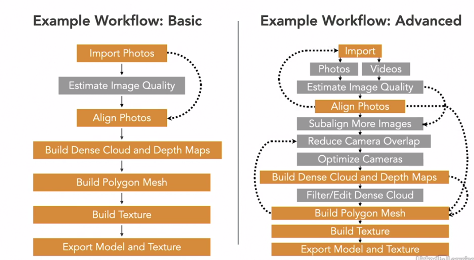
Gray steps are optional based on input sources and use case
Advanced Workflow
These are individual steps that can be done depending on use case and time. These fit into the steps from the [Basic Workflow] to improve the end result
Camera Calibration
- Can be important, especially if you lost the EXIF data
- Go to Tools->Lens->Show Chessboard, zoom to make sure at least 10×10 checkerboard is showing, take 3 pics of it from different angles. Keep the same focal length, make sure there’s no glare
- Ideally the entire area of each photo should be the calibration pattern.
- Workflow-> Add photos or Add folder to add in all the calibration photos
- Lens-> Calibrate lens
- Can see the factors once solved in Tools->Camera Calibration to reuse in other projects if wanted. These can be exported by going to File->Export->Export Cameras
Using video files
- Good to quickly capture low quality photogrammetry objects
- Should be a 360 round-the-object video
- Make sure you have the relevant codecs (can get codec packs from codecguide.com)
- File->Import->Import Video
- Choose where to save the images to
- Frame step = how often to export a frame
- Large / medium / small refers to amt of change in the scene b4 it exports another– to do with overlap, not frames. Better than static number if the camera movement wasn’t constant
- Frame step = how often to export a frame
- Now we have images and can treat them like any other images
- Typically ends up a lot more noisy / lower resolution than starting from pictures, but can be quicker to capture
Using masks to align a turntable capture
- NOTE: seems to not be as necessary now as long as during alignment, you check the “exclude stationary tie points” box
- BUT if that doesn’t work, can create a mask by clicking on a photo and using the tools in the toolbar. Only need to do so on one photo per camera/turntable position- best is to take a photo w/o the subject and use that entire photo as the mask. Then, in aligning, apply masks to Tie points
- To apply masks, click on a photo in the Photo pane (bottom of page), use a selection tool (between the Navigation and Region tools) to select the areas to mask, and Right click->Add Selection
Prealignment Settings
- Keeping Key points allows the option to add additional photos later w/o needing full realignment, increasing flexibility
- Tools->Preferences->Advanced->Keep Key Points, before we run alignment
- Good for if we realize some photos are missing or one part of the model isn’t in the photos
- Calibrate Camera
- Tools->Camera Calibration, before running alignment
- Can look at the settings for each camera used.
- Usually unnecessary to open- does its best to estimate the properties. Better if we calibrate as above, export the xml file, and use that
- If we know that certain properties are deffo correct, we can lock them in place so that Metashape doesn’t change them around while sensing the photos (usually f if no zoom, cx/cy)
Optimizing cameras w/ Metashape
- Right after aligning, can get best possible alignment and align any cameras that didn’t automatically align, or aligned poorly
- Model->Gradual Selection
- Criterion: Reprojection Error to select pts that have above a certain error factor
- Edit->Delete Selection to delete the points
- Tools->Optimize Cameras to rerun the camera position calculator
- Often have to repeat this process multiple times until the max error when you go to select it is low. Should be at max 0.5, though 0.4 is better.
If some photos didn’t align
- Only need to worry if these weren’t just the empty “background” pics meant for masks
- In the photos pane, select all the non-aligned photos. Right click, Reset Camera Alignment, Right Click, Align Selected Cameras.
Subaligning more photos
- Workflow-> add photos OR add folder
- Workflow->Align, make sure “reset current alignment” is not turned on
- Faster than running alignment from scratch
Improving alignment results
- If some points seem weirdly offset from where they should be, that can potentially be fixed
- Use a selection tool to grab those points, right click->filter photos by tie points
- This will select the cameras that generated those points
- Right click on any of those cameras in the photo pane and click View Matches
- Note the cameras it shares a lot of “valid” matches with
- Select all of the cameras with the incorrect tie points, as well as cameras with a lot of matches with those cameras. Right click, Reset Camera Alignments. Right click, Align Selected Cameras
Reducing overlap in Photosets
- Removing redundant images can make generating dense point clouds and generating meshes a lot faster
- First, generate a mesh from the sparse cloud
- Make sure cameras are showing (Model->Show/Hide Items->Show Cameras) so you can get a visual representation of cameras being temporarily removed
- Tools->Reduce Overlap
Filtering dense cloud points
- Sometimes, you’ll have some incorrect points that you want to remove
- On the menu bar, switch from Dense Cloud to Dense Cloud Confidence. This will colour the points based on how many photos they’re in– how confident the system is that that’s correct
- Get rid of them from Tools->Dense Cloud->Filter By Confidence
- Play around with the specific minimum confidence (can go back to that Tool and change the values)
- Once you have a good number for the minimum confidence, invert the interval (ie 5-255 -> 0-4, or 3-255 -> 0-2) using the same tool. Use a select tool to select all those points and delete them (Edit->Delete Selection).
- Tools->Dense Cloud->Reset Filter to get the rest of the model back
Estimating model confidence with depth map mesh
- This can tell you if there’s specific parts of your model that you should reshoot (and then subalign, etc etc)
- Right click on the model in the workspace, Duplicate
- Rename the italicized one (which is now hidden) as something like “Mesh from Dense Cloud”, just for clarity.
- Rebuild the mesh (Workflow->Build Mesh), this time using Depth Maps as the Source Data. Use the same other settings used for the original mesh.
- The Depth Map Mesh can be used for surface analysis, to see how reliable different parts of our model are
- Toolbar->Model->Model Confidence
- Might want to reshoot areas with low confidence (red/orange coloured areas)
- Can then delete the Depth Map Mesh
Colour calibration and texture building
- After you have a good mesh, some of the colours might still be splotchy, esp if lighting changed through the course of shoots
- Tools->Calibrate Colours
- Workflow->Build Texture as usual. Generating a texture will also help with splotchiness (and of course is necessary for the final mesh export)
Editing a Metashape mesh
No matter how well you took pictures or cleaned up in previous steps, you’ll need to edit the mesh at the end for most use cases. A lot of the steps above make editing the mesh a lot quicker, easier, or more possible
Set goals based on
- What is it for
- For us, usually VR
- Low poly
- If 3D printing
- Watertight
- Good topology
- For us, usually VR
- What software do we have and what can it do
- Metashape: basic edits
- Meshmixer: mostly meant for 3D printing but also has editing tools
- Rhino: lotsa plugins, gen purpose
- Maya: best for animation, rendering, simulation
- Geomagic: engineering, inspection, CAD
- How much time do we have?
Import a mesh to edit into Metashape
- File->Import->Import Model
Check on topology stats (do this often throughout the process to see progress)
- Tools->Mesh->View Mesh Statistics
- Having Open Edges is a problem if you need watertight meshes
- Similar Vertices is vertices that are very close to each other, which we might wanna reduce to reduce mesh size
- These should be 0s-
- Out of range indices
- Free vertices
- Duplicate faces
- Zero faces
- Degenerated faces
- Multiple edges
- Flipped normals
- Connected components refers to discrete meshes. If this is to be a watertight mesh, there should only be 1, but this could be a lot larger if you’ve captured terrain or a room with objects in it, etc
- Use their “Fix Topology” tool if possible, it might be able to automatically fix some stuff
Remove mesh fragments
- Sometimes, tiny little mesh chunks can form off of the model due to noise
- Can be selected with any selection tool and deleted, but almost always better to automate!
- Model->Gradual Selection
- Choose “Connected component size” for Criterion, use the slider to get rid of tiny chunks
- Edit->Delete
Manually select mesh faces
- Good for fine-tuned mesh changes
- Sometimes you’ll have little buds on a surface, or really bad discoloration due to noise
- Better to delete and then fill hole than try to fix any other way
- Use any selection tool to grab some faces to delete. Make sure you haven’t selected extra faces (the selection tool also grabs faces on the other side of a model, if there is one). Remove extra faces from the selection by shift-selecting them
- Use PgUp and PgDown to increase / decrease the size of the selection from your small initial selection
- Delete those faces
- Rinse and repeat until all of these are gone
Close mesh holes
- Needed for better geometry, and also for, for eg 3D printing
- Tools->Mesh->Close Holes
- If just want to close up small holes that you cut out from cutting out noise, can keep the slider small, or move it to 100% if you need watertight
- The results will be really chunky geometry, but we can fix that, esp bc the filled in faces are currently selected-
- Tools->Mesh->Smooth Mesh
- Apply to Selected Faces, and play around with strength or rerun until it matches the surrounding edges. Uncheck “fix borders” so that the entire fillins can change
Smooth mesh
- Can help with later reducing mesh size
- Can help undo noise from photos or processing
- Tools->Mesh->Smooth Mesh
- Apply to all faces
- Use very low strength (like 1) so that it doesn’t get nuked. This is not something that can be undone
Reduce poly count
- Helpful for most uses
- Essential for us (VR)
- Because this tool can’t be undone, duplicate the mesh by right clicking on the mesh in the Workspace and duplicating
- Rename the currently showing model (not italicized) something like “Low Resolution”
- Tools->Mesh->Decimate Mesh. Set target face count. If it gets rid of too many important features, delete that, reduplicate the original mesh, and try again with a higher face count.
- For VR or any low-poly uses: If it still looks good and like it could lose more resolution, run the tool with a lower target face count. Repeat until you find the lowest face count that results in a mesh that is amenable to you
- Most 3D printer programs have a max poly count that they can use. You can use this or any lower number as your target face count
- One really good to both get a low poly mesh and a realistic looking one is to generate a normal map with the high-definition model, and use that on the low-def model in whatever platform you use
- Workflow->Build Texture
- Set Texture Type to Normal Map
